EN
EN

Aluminum Profile Accessories:
How to Choose Brackets, Nuts and Bolts
A practical selection guide to slot compatibility, joint performance and reliable assembly.
A workbench, machine enclosure or automation frame can still wobble even when the profile size is correct. The cause may be the joints: poorly positioned brackets, incorrectly seated T-slot nuts or bolts that bottom out before clamping can all compromise the connection.
Select accessories in this order: profile interface, connection method, fasteners, then verification under operating conditions. First establish compatibility, then assess joint strength and stiffness, and finally confirm assembly and maintenance access.
Check the slot geometry, not just “4040”
Designations such as 4040 and 4080 mainly describe the external cross-section dimensions. They do not uniquely identify compatible accessories. Even 40-series profiles with nominal 8 mm slot openings may differ in cavity shape, slot lips, radii and center bore. Market labels such as “European standard” or “Chinese standard” do not replace a cross-section drawing.
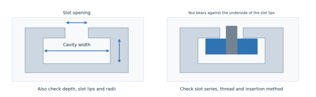
Figure 1. How a nut fits the slot. This simplified local section does not represent a complete profile or actual dimensions.
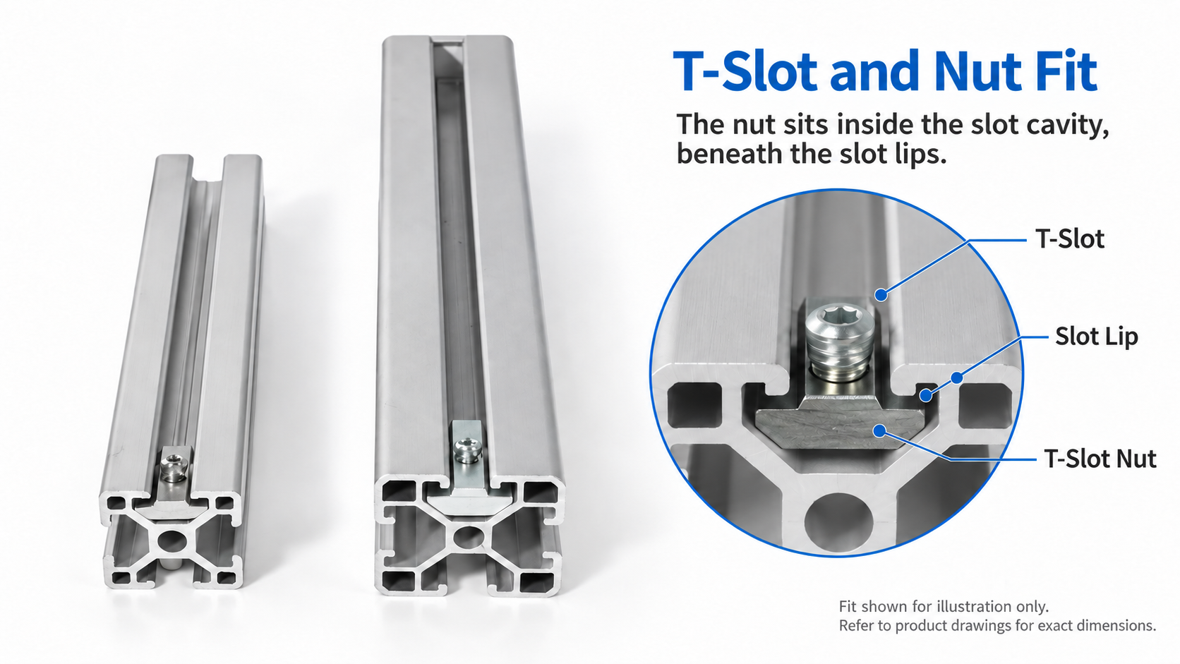
Before ordering, check the full profile model and drawing, slot opening and cavity dimensions, nut series and thread, bracket hole diameter and spacing, and any machining required for the connector. Slot 8 identifies a slot system; M8 identifies a thread. They are not interchangeable specifications.
Confirm the profile drawing together with the proposed accessory drawings instead of ordering only “a bracket set for 4040.” When mixing brands, test a sample assembly first.
Internal and external joints: how loads are transferred
“Internal connector” describes a mounting location, not a single design. It can include concealed corner connectors, end-bolt fasteners, anchor fasteners and automatic fasteners. Their load paths, machining requirements and capacities vary substantially, so selection must be based on the specific product.
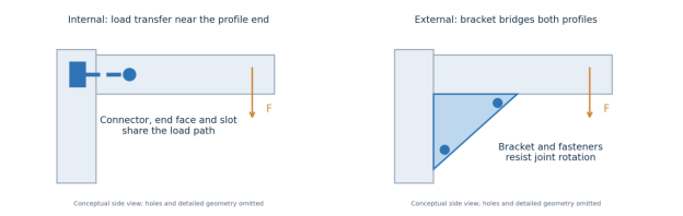
Figure 2. Conceptual load paths in internal and external connections. Dashed lines indicate concealed fastening; arrows show example external loads.
Internal joints: end clamping and anti-rotation features
Many end-clamping designs pull the end face of one profile against the side of another. Performance depends on preload, end-face contact, the number and spacing of fastening points, and the capacity of the slot or central thread. These connections offer a compact appearance and leave more space around the corner.
Concealed does not mean suitable only for light loads. Manufacturers offer paired automatic fasteners with resistance to sliding, torsion and bending. The performance of a small internal corner connector cannot represent all internal connection systems. [1]
External brackets: stiffness and fastener placement
An external bracket bridges two profiles. Loads pass through the bracket body and the bolts and nuts on both sides into the slots. Ribs, longer arms or multiple fastening points can help limit joint rotation. Actual performance still depends on bracket deformation, hole layout and the strength of the profile’s slot lips.
Distinguish at least three loading cases: sliding along the slot, outward pull-out and bending moment. A 100 N load acting at a perpendicular lever arm of 0.30 m produces 30 N·m; at 0.60 m, it produces 60 N·m. These are mechanics examples, not accessory ratings. Some brackets have limits for both force and moment, and both must be satisfied. [2]
Do not specify a bracket only by asking how many kilograms it can support. Provide the load direction, application point, cantilever length and vibration conditions, then check the relevant joint data.
Choosing brackets and installing connections
Standard brackets, reinforced brackets and joining plates
Standard angle brackets are candidates for general framing joints, with straightforward installation and adjustment. Ribbed brackets may suit locations where joint deformation must be limited, but “extra thick” alone is not a performance rating. For larger profiles, eccentric loads or cantilevers, also compare larger brackets, multi-hole joining plates and diagonal braces.
Match bracket hole diameters to the bolts and hole spacing to the profile slot centers. Locating bosses or tabs must also fit the slots. Leave room for tools and check for interference with panels, hinges, sliders and the operating area.
|
Criterion |
Internal connectors |
External brackets |
|
Space and appearance |
Compact joint; some designs occupy slot space |
Occupy corner space; visible fasteners |
|
Profile machining |
Some require drilling or tapping; others need no pre-machining |
Common T-slot nut designs need no drilling |
|
Later adjustment |
Depends on connector design and tool access |
Usually easy to loosen, reposition and retighten |
|
Capacity assessment |
Specific connector design and manufacturer joint data |
Combined bracket, fastener and slot data |
This comparison is a selection overview. Confirm machining and installation requirements for the specific model. [3]
External brackets: align first, then tighten as specified
Insert compatible T-slot nuts in the planned assembly sequence. Fit the bolts on both bracket faces loosely so the joint remains adjustable. Check squareness, position and frame diagonals. Once both faces sit flush, tighten in the specified sequence and to the specified torque. Verify that post-insertion nuts have rotated or rolled fully into their correct bearing position.
Internal connectors: check machining and assembly order
Where machining is required, tap the profile end and prepare connection or tool-access holes to the drawing, then remove burrs and chips. Fit automatic fasteners that require no pre-machining according to their own instructions. Align and lock the profiles, checking end-face contact and anti-rotation features. Internal connections do not all share the same drilling requirements. [3]
Do not omit specified bolts at critical joints. Adding bolts also does not guarantee a proportional increase in capacity: load distribution and local profile deformation must be checked.
Select nuts and bolts as a matched assembly
Choose nuts by slot, insertion method and capacity data
Pre-insertion slide-in nuts usually enter from the profile end and are fitted before the frame is closed. Compatible post-insertion nuts can rotate or roll into the slot at an intermediate position, making later additions easier. Spring clips or spring-loaded balls help hold a nut in position, but these features do not establish its load rating. Insertion options depend on the specific design. [4]
“T-nut” terminology varies between catalogs. Specify the slot series, thread, insertion method, material and exact model instead of relying on appearance. Assess the nut body, bolt and profile slot lips as one system. [4]
Choose the thread and head type, then check bolt length
Socket head cap screws are common in brackets and connectors. Low-head and countersunk screws require matching holes, counterbores or countersunk seats. A T-bolt locks its head inside the slot and uses a nut outside; this is a different arrangement from a standard bolt with a T-slot nut.
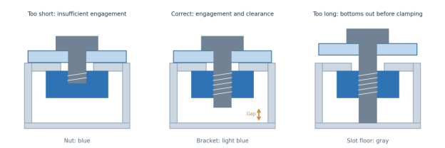
Figure 3. Bolt-length checks for a standard bolt and T-slot nut. Not to scale; use the matched component drawings to determine engagement requirements.
Satisfy two conditions at once: sufficient effective thread engagement and clearance that prevents the bolt tip from reaching the slot floor or blind-hole bottom before clamping. Account for bracket and washer thickness, the nut’s position in the slot and the required engagement. Most non-countersunk bolts are measured from the head’s bearing face; countersunk screws are generally specified by overall length. Check the applicable drawing.
A bolt that is too short reduces engagement; one that is too long can feel tight without clamping the joint. Confirm property class, material and finish as a set. Stainless steel does not automatically mean higher strength. Use the torque specified for the connection system rather than applying a generic steel-bolt torque table directly to an aluminum profile slot.
Match the connection to the application
|
Application |
Connection options |
Key checks |
|
Workbenches and general frames |
External brackets; plates or braces where needed |
Lateral sway, beam-end stiffness and adjustment space |
|
Machine enclosures and panel frames |
Internal connectors; brackets where space permits |
Panel interference, tool access and door loads |
|
Cantilevers and large eccentric loads |
Reinforced brackets, multiple fastening points or validated internal joints |
Bending moment, pull-out, slot lips and local deformation |
|
Vibrating equipment and mobile frames |
Joints and locking methods rated for the conditions |
Cyclic loads, impacts and inspection access |
These are selection directions based on assembly and loading characteristics, not load ratings for specific accessories.
Example: specifying a complete accessory set for a 4040 workbench
Obtain the exact 4040 cross-section drawing and confirm the slot series. Select the joints according to the worktop load, beam span and lateral forces. If using external brackets, match the bracket holes, nut model, thread size, bolt head and bolt length as one set, and confirm whether washers are required.
If the workbench sways sideways, also examine diagonal bracing, beam layout and foot anchoring. Larger bolts alone do not guarantee a stiffer frame. During trial assembly, check insertion, face contact, tool access and tightening, then verify structural performance under the intended operating load.
Provide a complete brief when requesting a quotation
Send the supplier the profile model or cross-section drawing, a joint sketch, loads and application points, static or vibration conditions, machining constraints, and panel and maintenance clearances. Ask for complete accessory model numbers, machining drawings, installation torque and applicable conditions to create a reusable bill of materials.
Reliable accessory selection means matching brackets, nuts and bolts to the profile interface as a complete system. Correct fit, a clear load path and proper installation support efficient assembly, stable operation and easier maintenance.
Table of Contents
- Check the slot geometry, not just “4040”
- Internal and external joints: how loads are transferred
- Internal joints: end clamping and anti-rotation features
- External brackets: stiffness and fastener placement
- Choosing brackets and installing connections
- Standard brackets, reinforced brackets and joining plates
- External brackets: align first, then tighten as specified
- Internal connectors: check machining and assembly order
- Select nuts and bolts as a matched assembly
- Choose nuts by slot, insertion method and capacity data
- Choose the thread and head type, then check bolt length
- Match the connection to the application
- Example: specifying a complete accessory set for a 4040 workbench
- Provide a complete brief when requesting a quotation