EN
EN

INDUSTRIAL AUTOMATION FIELD GUIDE
How to Choose Aluminum Profile Series for Automation Equipment Frames
A practical guide to load, span, dynamic motion and structural design
Industrial aluminum profiles are widely used for automation equipment frames, machine enclosures, workstations, conveyor systems, robot cells and linear motion structures. Their modular design shortens fabrication time, simplifies assembly and makes future modifications much easier than welded steel structures.
However, choosing an aluminum profile is not simply a matter of selecting the largest section available. An undersized frame can flex, vibrate, loosen at the joints or reduce positioning accuracy. An oversized frame increases material, machining and assembly costs without necessarily improving the parts of the machine that actually matter.
The right approach is to select the profile series according to the load path, unsupported span, motion conditions and function of each structural area.
 1. Divide the Equipment into Structural Zones First
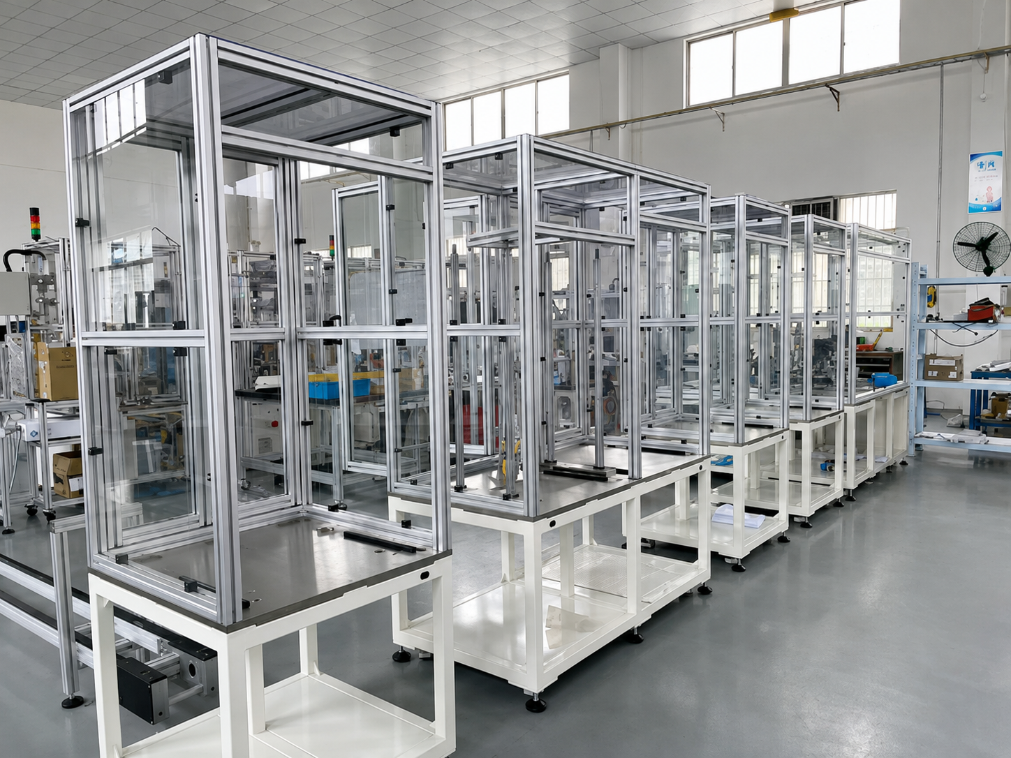
A complete automation machine does not need one profile size everywhere. In most cases, the frame can be divided into four zones:
- Enclosures and light-duty accessories – safety guards, doors, cable supports, display mounts and sensor brackets. These parts mainly provide protection or mounting positions.
- Main machine frame – the structure that supports the enclosure, fixtures, worktable and standard machine components.
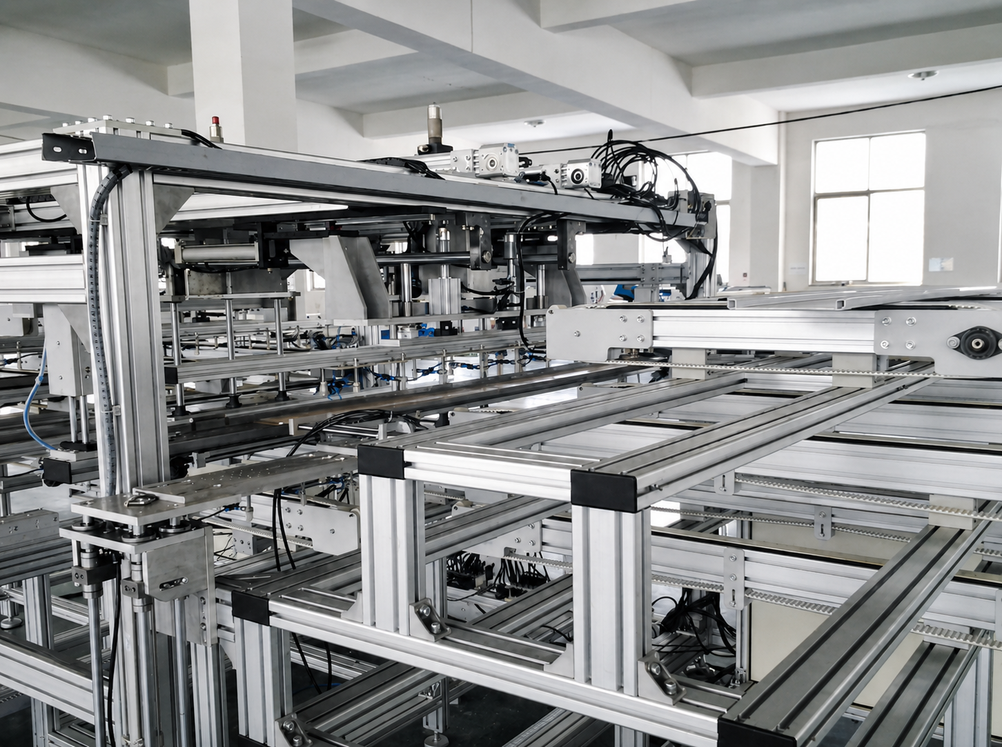
- Motion-system support beams – beams carrying linear modules, belt drives, ball-screw axes, pick-and-place units or conveyor drives.
- Heavy-duty bases and long-span structures – foundations for heavy workpieces, robot cells, long conveyors and large automated production equipment.
Using a larger profile only where it is structurally needed produces a frame that is both stable and cost-effective. For example, a 3030 or 4040 profile may be suitable for an enclosure, while the beam that carries a moving linear module may need 4080 or 40120.
 2. Four Factors That Determine the Correct Profile Series
2.1 Load: Consider How the Load Is Applied
Do not look only at the total machine weight. The more important questions are:
- Is the load evenly distributed or concentrated at one point?
- Is the profile used as a simple support beam or as a cantilever?
- Does the structure carry a static load only?
- Will it experience repeated acceleration, braking, impact or vibration?
- Is there a required positioning accuracy or allowable deflection?
A fixture weighing 50 kg on a short, well-supported worktable creates a very different structural demand from the same 50 kg moving at high speed on a long beam. Concentrated loads and cantilever loads require stronger sections than evenly distributed static loads.
For moving equipment, the frame should be selected based on the maximum working load and the actual operating cycle—not only the nominal payload of the component.
2.2 Span: Longer Beams Need More Stiffness
Span is one of the most frequently overlooked factors in aluminum frame design. A 4040 profile may be sufficiently rigid over a short distance, but the same profile can show noticeable deflection when used as a long unsupported beam with a center load.
Even small deflection can affect:
- Parallelism between guide rails;
- Belt tracking and conveyor stability;
- Repeat positioning of a linear module;
- Alignment between fixtures and tooling;
- Long-term joint tightness and machine noise.
When a beam becomes longer, the usual solutions are to increase the profile section, add intermediate supports, reduce the unsupported span, use paired profiles, or redesign the structure so loads are transferred through a closed frame rather than a single beam.
2.3 Dynamic Conditions: Motion Creates Additional Forces
Linear modules, conveyors, lifting units and robots generate more than static weight. During fast starts, stops and direction changes, inertia can create vibration and transient loads that are much higher than the load seen while the machine is stationary.
If a motion beam is too flexible, common symptoms include vibration during travel, increased operating noise, inconsistent repeatability and joints that gradually loosen. For this reason, a motion-system beam is often selected one level above the profile used for the surrounding enclosure or general frame.
For high-speed or high-precision equipment, the final design should be verified through engineering calculations or structural simulation.
2.4 Connections: A Strong Profile Still Needs a Strong Joint
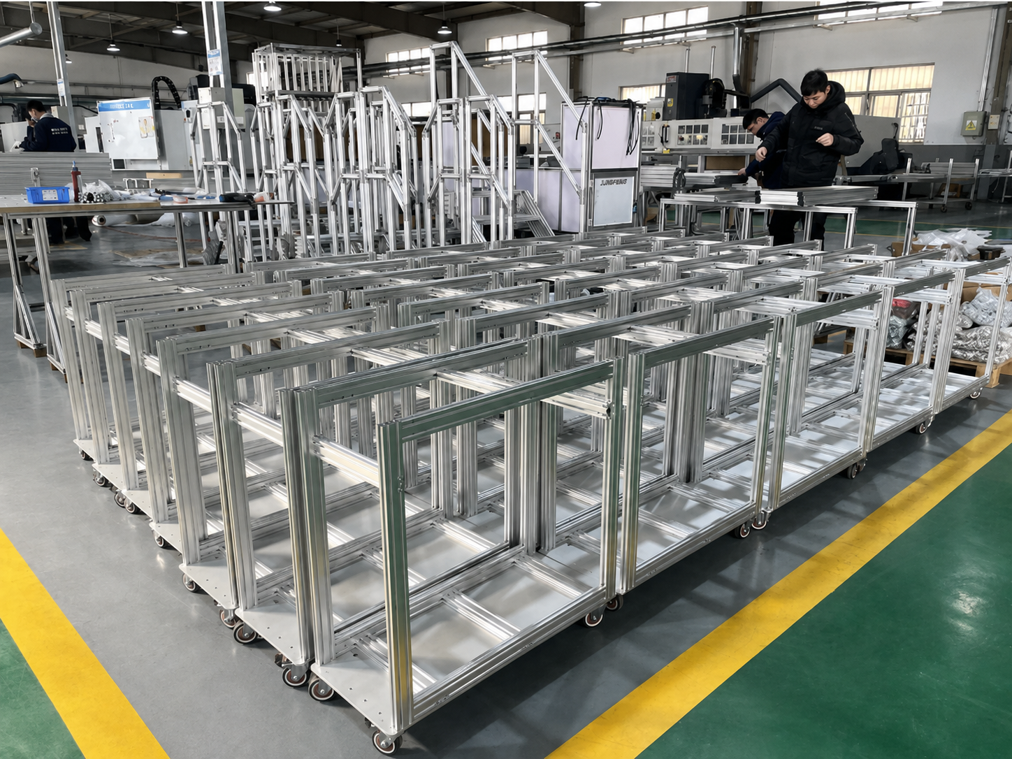
Frame stiffness depends on both the profile section and the connection method. Standard corner brackets are convenient for light-duty guards and covers, but heavy machine bases and moving structures usually require stronger internal connectors, end-tapped fasteners, thick gusset plates or reinforced brackets.
Tall frames, long beams and structures with reciprocating motion should also use cross bracing, triangular gussets or transverse members where appropriate. A well-designed connection layout can improve stability more effectively than simply increasing the profile size.
 3. Common Aluminum Profile Series and Typical Applications
|
Profile Series |
Key Characteristics |
Typical Automation Applications |
|
2020 / light-duty 2020 |
Compact, lightweight and economical |
Small covers, sensor brackets, cable supports, tabletop devices |
|
2040 / 2060 |
Better bending resistance in one direction |
Light-duty machine beams, door frames, monitor mounts, compact workstations |
|
3030 |
General-purpose, balanced strength and weight |
Small automation machines, inspection fixtures, light workstations, guard frames |
|
3060 / 3090 |
Suitable for directional loading and longer members |
Small conveyors, uprights, door frames and auxiliary module supports |
|
4040 |
A common main-frame choice for automation equipment |
Medium-duty machine frames, worktables, fixture platforms and equipment bases |
|
4080 / 40120 |
Higher bending stiffness for larger spans |
Conveyor main beams, linear-module support beams, large machine crossmembers |
|
5050 / 50100 / 50150 |
Heavy-duty sections with high overall stability |
Robot-cell frames, heavy workstations, long-span equipment bases |
|
100100 / 120120 and above |
High rigidity and torsional resistance |
Large production lines, heavy automation equipment and large safety enclosures |
The series above are a practical starting point. The final selection still depends on wall thickness, actual profile geometry, alloy condition, connection design and the exact loading arrangement.
 4. Reference Selection by Equipment Type
Small Inspection Machines and Vision Systems
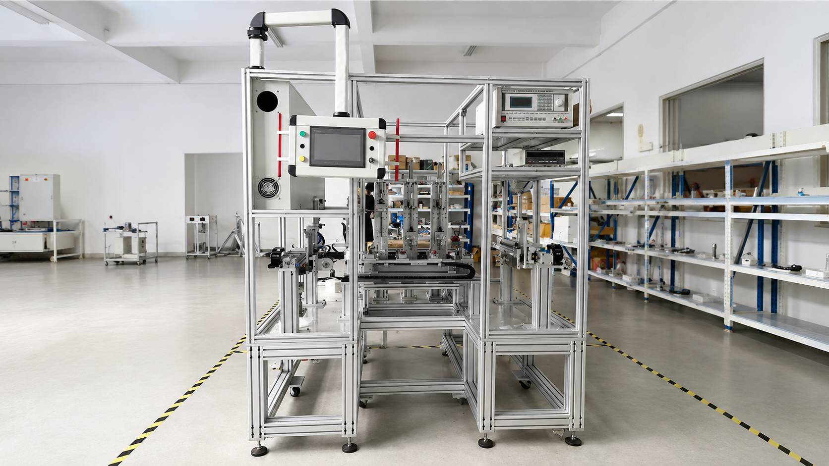
Compact inspection equipment often includes cameras, lighting, fixtures and small linear modules. The overall weight may be modest, but optical or motion components can still require a stable mounting surface.
Typical configuration:
- Enclosure and door frame: 2020, 2040 or 3030;
- Main frame: 3030 or 4040;
- Linear-module mounting beam: 4040 or 4080;
- Base: 4040 with leveling feet and reinforced joints when needed.
For vision systems, avoid thin profiles or long cantilevers at camera and motion-module mounting points. Structural vibration can directly affect image stability and inspection repeatability.
Screwdriving, Dispensing and Labeling Machines
These machines typically use XYZ motion systems with frequent acceleration and deceleration. The motion structure should therefore receive more attention than the exterior cover.
Typical configuration:
- Enclosure and safety door: 3030 or 4040;
- Main machine frame: 4040;
- X- and Y-axis support beams: 4080 or 40120;
- Base: 4040, 4080 or 5050 depending on equipment size and payload.
For large-travel dispensing machines or multi-axis screwdriving systems, select the module support beam based on travel length, moving mass and acceleration first, then design the outer frame around it.
Belt Conveyors, Roller Conveyors and Pallet Conveyors
For conveyor systems, the key variables are conveyor length, support spacing, unit load, transfer method and drive layout.
Typical configuration:
- Light-duty belt conveyors: 3030, 3060 or 4040;
- Medium-duty roller conveyors: 4040 or 4080;
- Accumulation or pallet conveyor structures: 4080, 40120 or 50100;
- Heavy-duty pallet transport: 40120, 50150, 100100 or larger sections;
- Supports and legs: 4040, 4080 or 5050, selected according to height and load.
Long conveyors require a sensible leg spacing and adequate cross bracing. Increasing the profile size alone cannot fully compensate for excessively large support intervals.
Robot Workstations and Safety Cells
A robot workstation usually includes a robot base, fixtures, perimeter guarding and a control-cabinet area. These elements should not be designed to the same structural level.
Typical configuration:
- Safety guards: 2020, 3030 or 4040;
- Guard doors: 3030 or 4040;
- Control-cabinet supports: 3030 or 4040;
- Fixture table: 4040, 4080 or 5050;
- Robot base: a heavy-duty aluminum frame with thick connection plates and floor anchors, or a welded steel base where required.
Robot base design must consider dynamic inertia, reach, payload and cycle speed—not just the robot's own weight. High-speed or high-payload robots often require a steel base or a heavily reinforced and floor-anchored aluminum structure.
 5. Four Common Selection Mistakes
Mistake 1: Selecting by Total Machine Weight Only
The same total weight can create very different stresses depending on where it is placed. Span, support position, concentrated loads and cantilevers must be considered together.
Mistake 2: Using One Profile Size for the Entire Machine
Using one series everywhere may simplify purchasing, but it often wastes material in light-duty areas and leaves key load-bearing areas under-designed. A zoned design is usually more economical and more reliable.
Mistake 3: Ignoring Doors and Cantilevered Accessories
Doors, HMI arms, control boxes and monitor mounts may not be heavy, but their load acts at a distance from the support point. Use profiles with a suitable orientation and adequate section size to prevent sagging and sway.
Mistake 4: Enlarging Profiles Instead of Improving the Structure
When stiffness is insufficient, a larger profile is only one option. Adding a center support, shortening the span, using a closed-frame design or improving the joint layout can achieve better results at lower cost.
6. A Practical Selection Workflow
Use the following workflow when designing an automation equipment frame:
- Define the overall equipment dimensions, machine weight and maximum workpiece load.
- Divide the structure into enclosure, main frame, motion beam and base zones.
- Identify the span, support points and loading direction of each member.
- Check for dynamic motion, impact, off-center loading and cantilevered components.
- Select a preliminary profile series for each zone.
- Design the connection method, gussets, crossmembers, leveling feet and floor anchors as part of the structure.
- Perform calculation or simulation for long-span, heavy-duty or high-precision equipment.
- Reserve T-slots and mounting positions for future pneumatic lines, cable routing, control cabinets, sensors, guards and fixtures.
Conclusion
The best aluminum profile series for an automation equipment frame is not necessarily the largest one. Light-duty covers and guards can often use 2020, 2040 or 3030 profiles. 3030 and 4040 are practical choices for many small and medium machine frames. For long spans, conveyor beams and linear-motion supports, 4080 and 40120 provide greater bending stiffness. Heavy equipment bases, robot cells and large production lines may require 5050, 50150, 100100 or larger sections, often combined with reinforced connections and floor anchoring.
For a reliable final design, provide the equipment size, load, span, operating speed, required accuracy and installation conditions to the engineering team or profile supplier. This makes it possible to match the profile section, connection method and support layout to the real application—and avoid costly frame modifications later.
Table of Contents
- 1. Divide the Equipment into Structural Zones First
- 2. Four Factors That Determine the Correct Profile Series
- 2.1 Load: Consider How the Load Is Applied
- 2.2 Span: Longer Beams Need More Stiffness
- 2.3 Dynamic Conditions: Motion Creates Additional Forces
- 2.4 Connections: A Strong Profile Still Needs a Strong Joint
- 3. Common Aluminum Profile Series and Typical Applications
- 4. Reference Selection by Equipment Type
- Small Inspection Machines and Vision Systems
- Screwdriving, Dispensing and Labeling Machines
- Belt Conveyors, Roller Conveyors and Pallet Conveyors
- Robot Workstations and Safety Cells
- 5. Four Common Selection Mistakes
- Mistake 1: Selecting by Total Machine Weight Only
- Mistake 2: Using One Profile Size for the Entire Machine
- Mistake 3: Ignoring Doors and Cantilevered Accessories
- Mistake 4: Enlarging Profiles Instead of Improving the Structure
- 6. A Practical Selection Workflow
- Conclusion