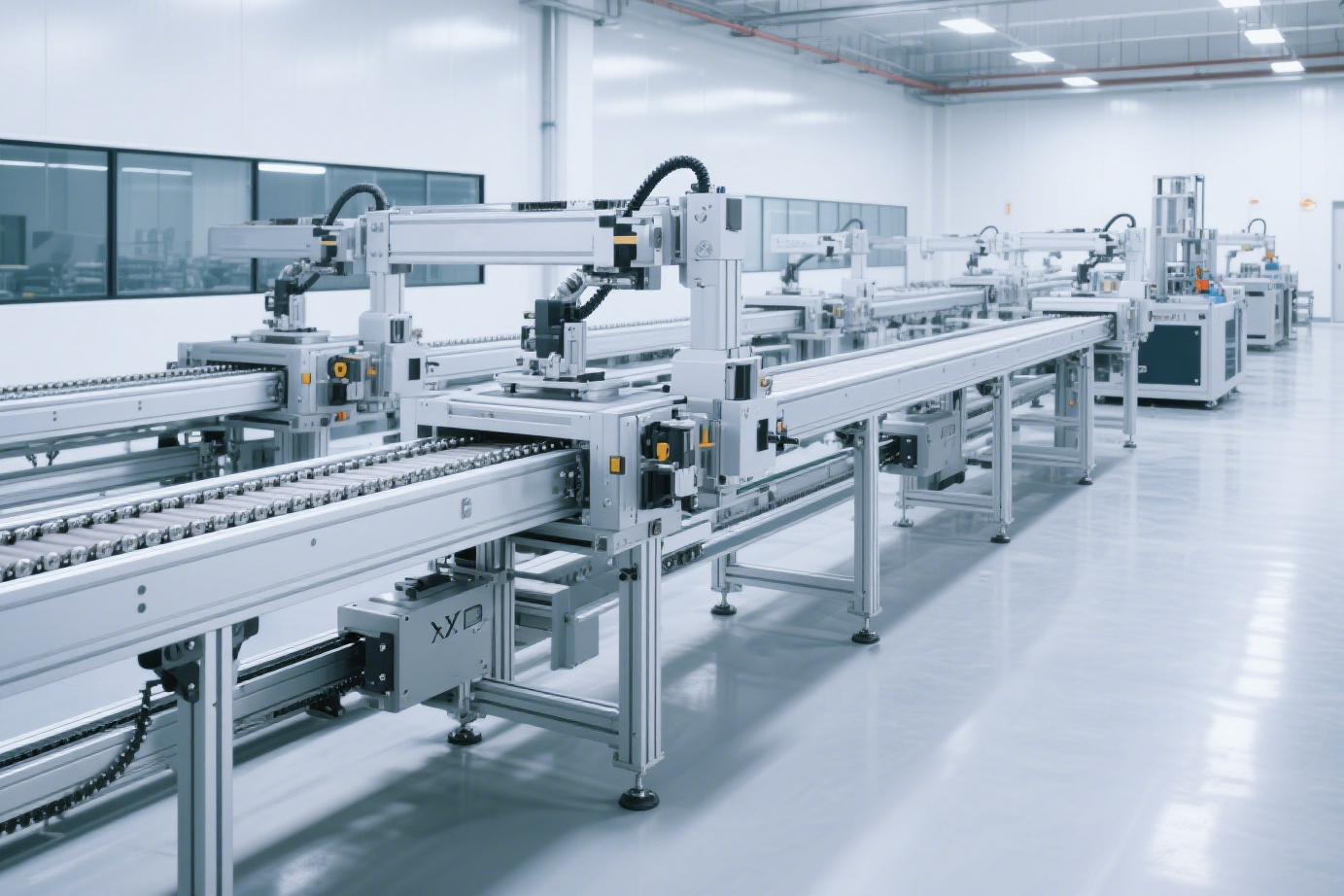
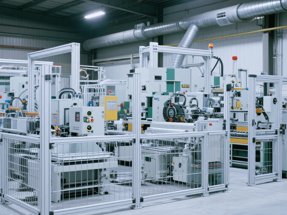
EN

New: E-CVBTA86 Economical Flat Belt Conveyor, Customized to Fit Your Line
A flat belt conveyor for transfers between machines, with its layout and drive arrangement planned around your site.
On an automated production line, a conveyor has to fit between upstream and downstream equipment. Available length, transfer height, material flow, and drive-end clearance all shape the layout. This is especially true in retrofit projects, where a standard size may not match the space already available. Confirming site conditions first helps define the conveyor body and configuration.
The E-CVBTA86 Economical Flat Belt Conveyor is designed for transferring materials between machines and can be customized to project requirements. The images show the complete unit, its drive end, and the roller-end structure.
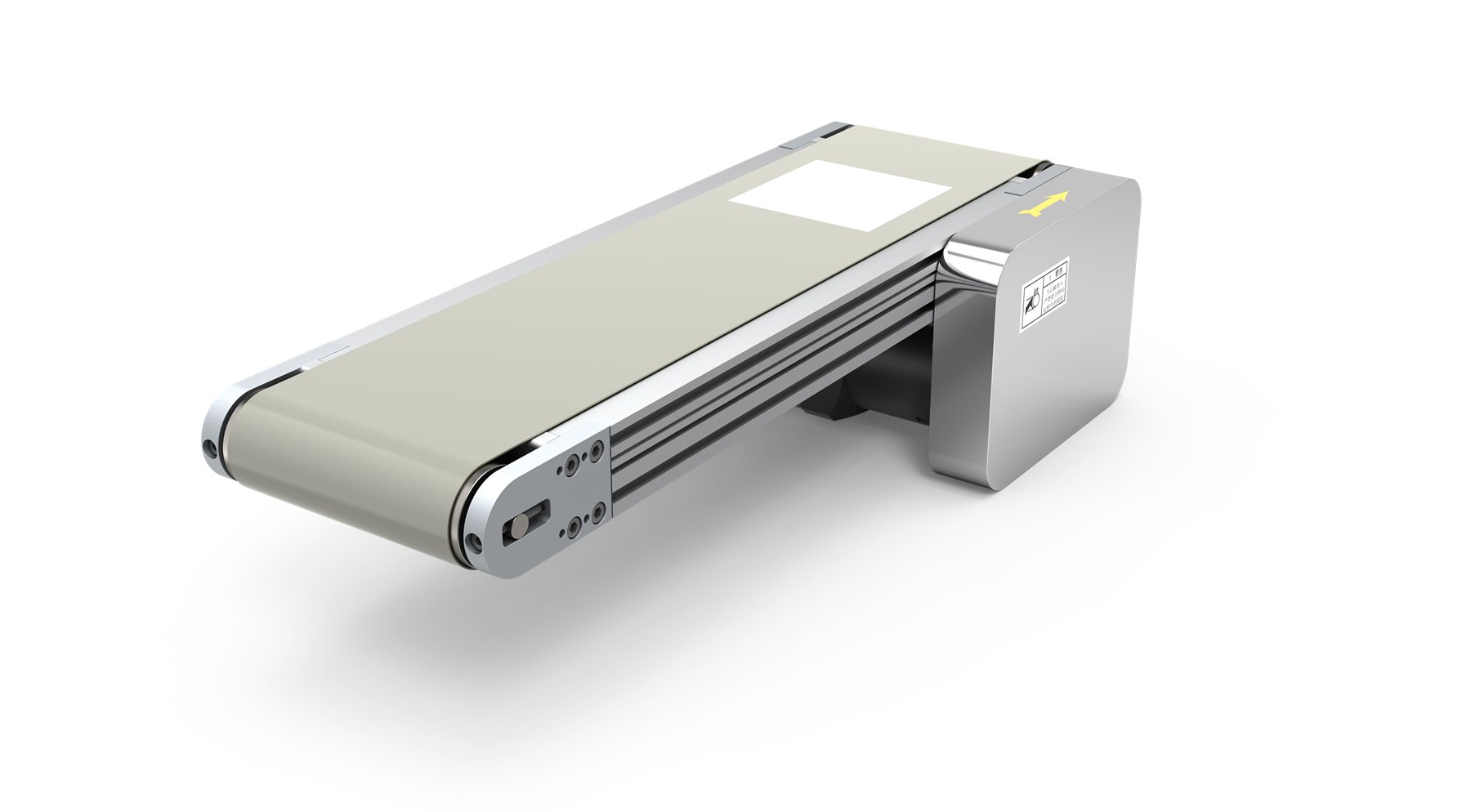 E-CVBTA86 Economical Flat Belt Conveyor
Plan the Transfer Section Around the Line
The flat belt runs along the top of the frame and around rollers at both ends. When connecting the conveyor to existing equipment, confirm the transfer points and belt height, then determine the conveyor length and mounting arrangement. It also helps to establish which end receives the material and where it is discharged.
For a line connecting several machines, a layout drawing helps show each conveyor section, its interface points, and the direction materials will move.
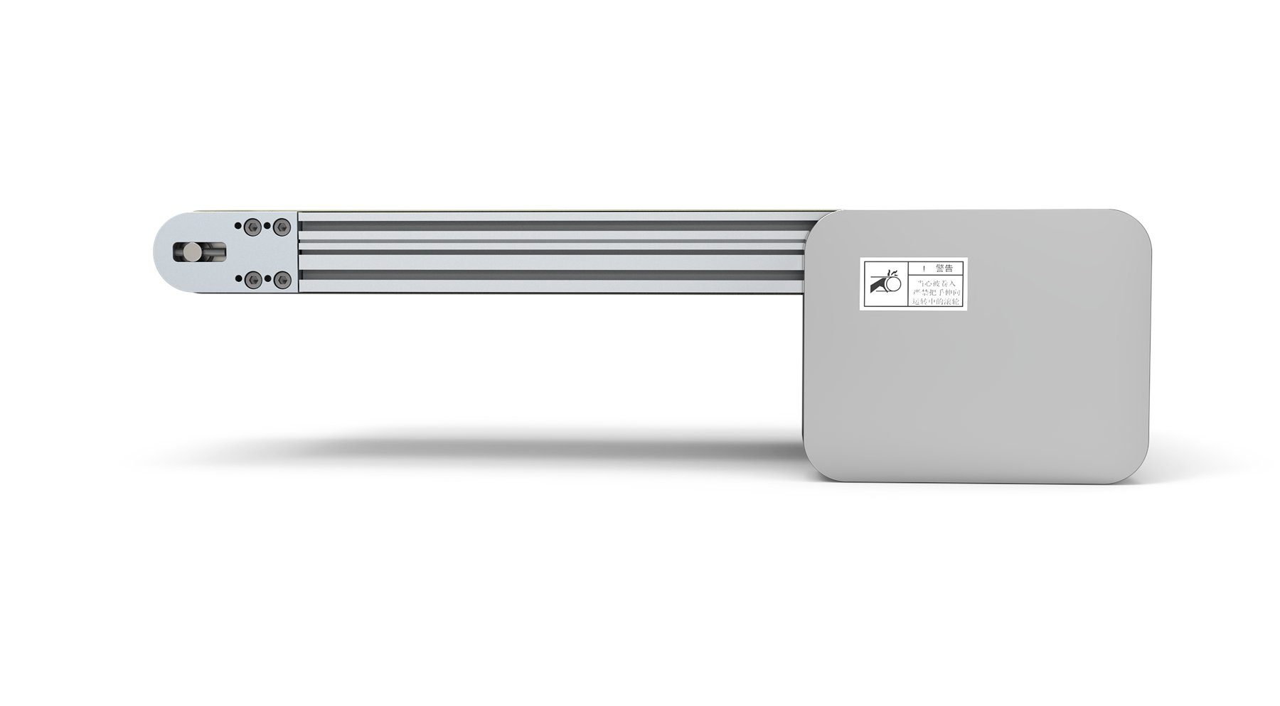 Side view: belt, frame, and end components
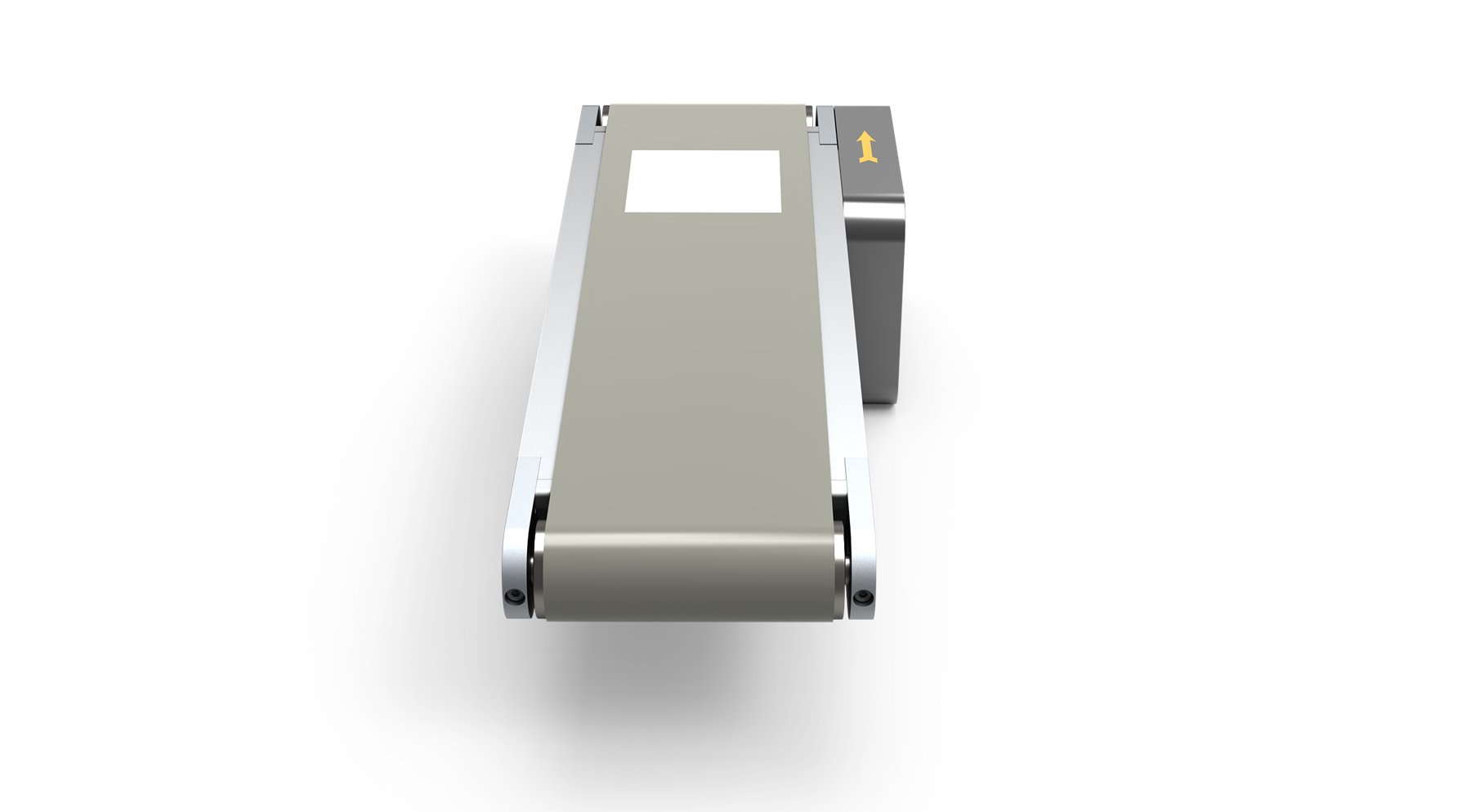 End view: belt and side frames
Position the Drive and Roller Ends for the Site
The illustrated configuration uses a head-end drive, with the drive assembly mounted below one end of the conveyor. During layout, check the drive orientation, clearance from adjacent equipment, and maintenance access to avoid interference with the surrounding line.
At the opposite end, the roller, end plate, and adjustment assembly need to suit the belt-end and frame layout. Final dimensions and mounting details should be confirmed against the project drawing. The following views show the underside, drive enclosure, and roller-end arrangement.
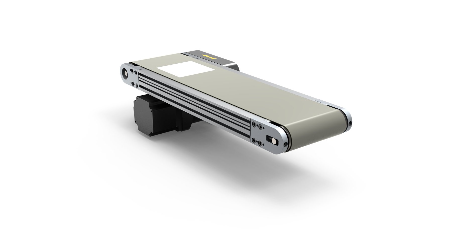 Underside: drive assembly in relation to the conveyor frame
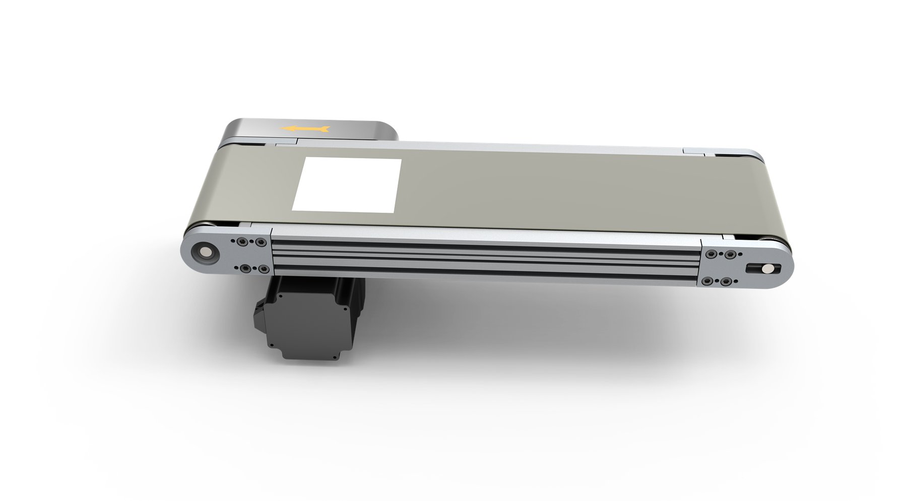 Front view: belt, frame, and end components
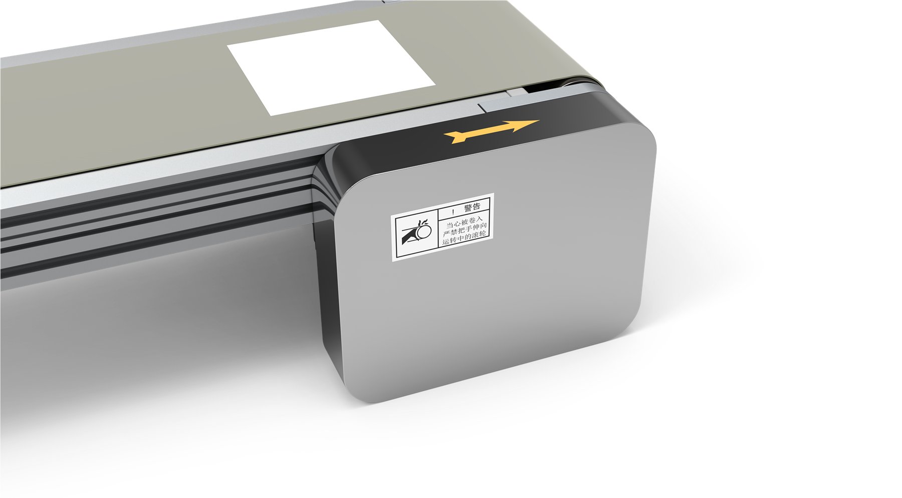 Head-end drive enclosure
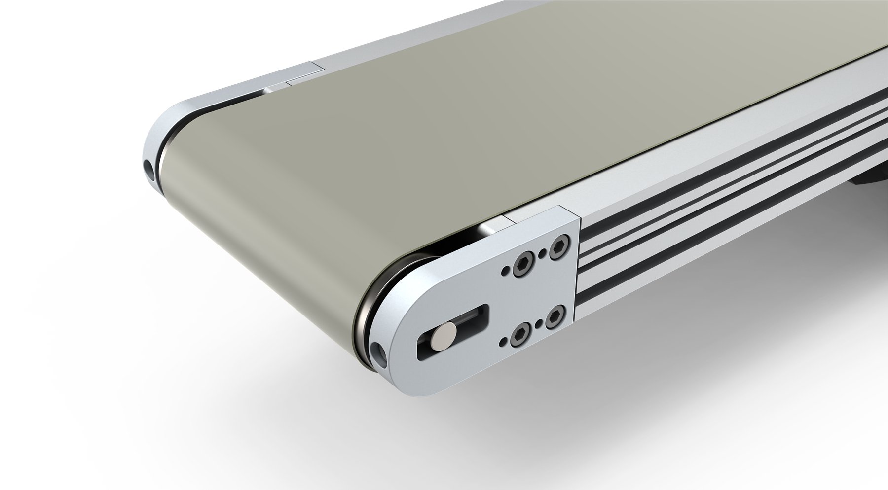 Roller end and adjustment assembly
Example Configuration
This example shows the listed configuration. Final dimensions and setup should be confirmed against the project requirements.
Illustrated configuration: Crowned rollers for belt tracking | Roller diameter: 50 | Head-end drive | Customizable
Model: HD-E-CVBTA86-100-540-80-100-4.5-RS-3-K9-LS-H
If you are planning a transfer section between machines, share a site layout or equipment drawing along with the transfer points, conveying direction, and material details. We can then review the conveyor structure and configuration against the available space and line requirements.
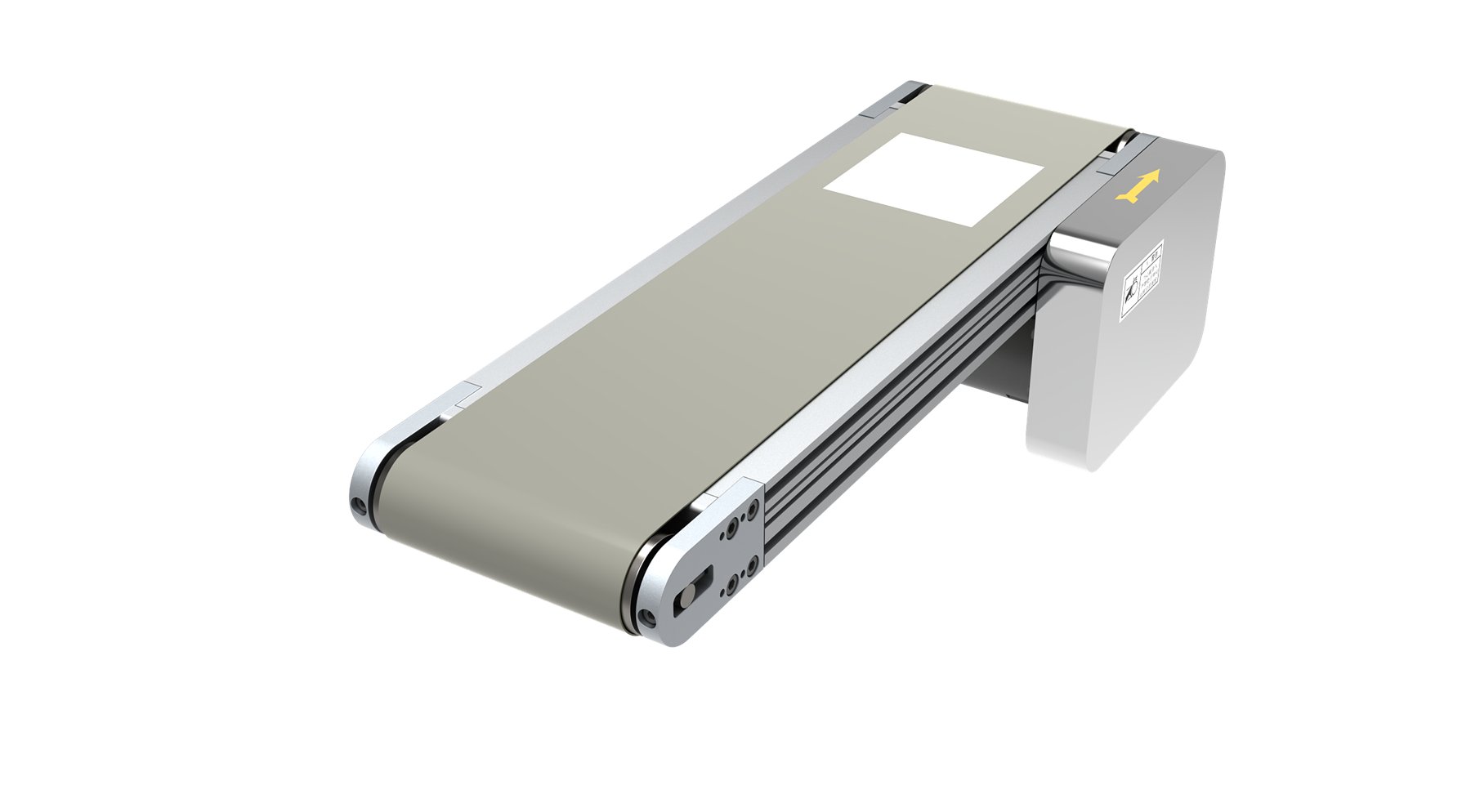 Overall view of the E-CVBTA86 conveyor