EN
EN

Henton PFC Pallet Backstop Components
PFC01 / PFC21 Series · Multiple Sizes and Mounting Options for Pallet Conveyor Systems
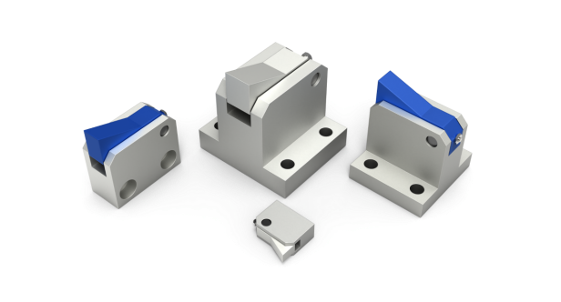 PFC series backstop components in multiple sizes and structures
In pallet conveyors, accumulation conveyors and automated transfer equipment, a pallet may still move slightly after it has been stopped or positioned. Conveyor inertia, vibration, contact between mechanisms, or movement from an adjacent station can cause a small rebound or backward shift.
On an ordinary transfer section, a few millimeters may not matter. At a locating, inspection, assembly, lifting or transfer station, however, that small movement can interfere with the next operation.
For this reason, many pallet conveyor systems add a simple mechanical safeguard at critical positions: a pallet backstop component.
Henton's PFC01 and PFC21 series use a spring-loaded pawl structure and are available in different pawl materials, body sizes, working strokes, spring-load ranges and mounting styles. The purpose of the range is not to create unnecessary model numbers, but to match the very different mechanical conditions found in real automation equipment.
1. A Mechanical Backstop Against Pallet Rebound
A PFC backstop unit is mainly composed of a pawl, a spring and a mounting base. As the pallet moves in the normal conveying direction, it presses the pawl down. After the pallet passes, the spring returns the pawl to its original position.
If the pallet then rebounds or shifts backward because of inertia, vibration or an external force, the returned pawl acts as a mechanical backstop and limits further reverse movement.
The unit is not intended to replace the conveyor drive, stopper cylinder, locating unit or lift-and-position mechanism. Its role is auxiliary protection: the primary mechanism performs the conveying, stopping and positioning, while the backstop adds an additional mechanical safeguard at positions where reverse movement is undesirable.
Because the action is purely mechanical, no extra cylinder, solenoid valve or control program is required. This makes the unit easy to integrate into pallet conveyors, accumulation conveyors, workpiece-carrier lines and similar automation equipment.
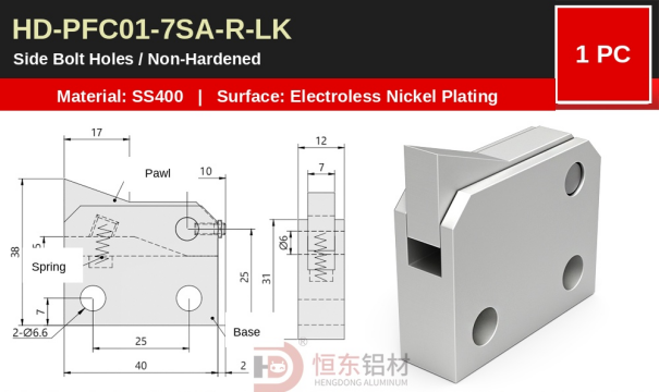 PFC01-7SA-R-LK: spring-loaded pawl and base integrated into one compact unit
2. PFC01 and PFC21: Metal Pawl vs. MC Nylon Pawl
The pawl repeatedly contacts the pallet during operation. For that reason, the material at the contact point matters, especially when different pallets have different surface finishes or damage requirements.
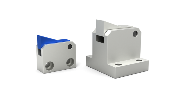 Metal-pawl PFC01 and MC-nylon-pawl PFC21
PFC01 · Metal Pawl
PFC01 uses a metal pawl. The currently listed Henton versions use SS400 for the metal body and are finished with electroless nickel plating. The product pages shown in this article are non-hardened versions.
This design is suitable for general industrial conveying, steel pallets, metal workpiece carriers and other applications where direct metal contact at the backstop point is acceptable. Its construction is straightforward and well suited to conventional mechanical backstop positions.
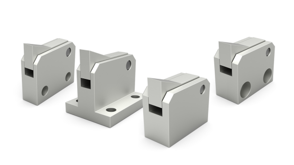 PFC01 series with metal pawls
PFC21 · MC Nylon Pawl
PFC21 replaces the pallet-contacting pawl with MC nylon while retaining a metal body. MC nylon is widely used for wear and contact components because it combines wear resistance with lower friction and a degree of impact damping.
For aluminum pallets, plastic pallets, anodized workpiece carriers, coated fixtures or any application where repeated metal-to-metal impact is undesirable, the nylon pawl provides a gentler contact surface. It can help reduce surface marking and the sharp impact noise produced by repeated metal contact.
PFC01 and PFC21 perform the same basic backstop function. The difference is how the pawl contacts the pallet: PFC01 is the standard metal-contact solution, while PFC21 is better suited to applications where surface protection and lower contact noise matter.
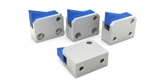 PFC21 series with blue MC nylon pawls
3. 7S, 7SA, 10S, 14S, 20S and 28S: Different Structures and Working Ranges
The PFC range currently includes 7S, 7SA, 10S, 14S, 20S and 28S specifications. These numbers should not be read simply as an outside-size sequence. Different versions change the body dimensions, pawl geometry, available working stroke and spring-load range.
|
Specification |
Representative body size |
Main structural difference |
|
7S |
Approx. 30 × 29 × 12 mm |
Compact structure for limited installation space |
|
7SA |
Approx. 40 × 38 × 12 mm |
Larger front profile while keeping a slim body |
|
10S |
Approx. 40 × 38 × 19 mm |
Thicker body and a wider range of mounting options |
|
14S |
Approx. 55 × 55.5 × 25 mm |
Supports larger working strokes and higher loads |
|
20S |
Refer to the model drawing |
Moves into a higher spring-load range |
|
28S |
Some BK versions approx. 40 × 38 × 12 mm |
High-load specification; outside size alone does not indicate load class |
7S is approximately 30 × 29 mm with a body thickness of about 12 mm. Its compact envelope is useful where the conveyor structure leaves very little room for the backstop.
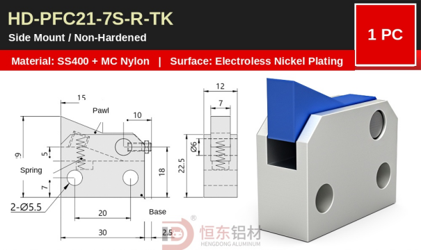 7S example: compact body, approximately 30 × 29 mm and 12 mm thick
7SA increases the front profile to approximately 40 × 38 mm while keeping the body around 12 mm thick. This gives more pawl structure without taking as much lateral space as a thicker unit.
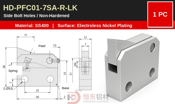 7SA example: approximately 40 × 38 mm and 12 mm thick
10S has a similar front profile of approximately 40 × 38 mm, but the body thickness increases to around 19 mm. It is also available with a particularly complete set of mounting structures, including through holes, counterbored holes, threaded holes, bottom threaded holes and a π-type base.
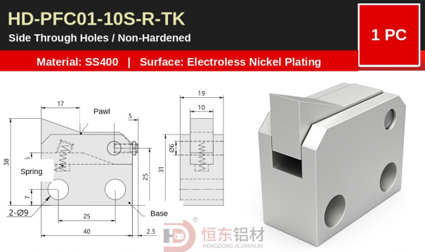 10S example: approximately 40 × 38 mm and 19 mm thick
14S increases to approximately 55 × 55.5 mm with a thickness of about 25 mm. It also begins to cover the longer Stroke 10 (12) load range, making it suitable for mechanisms that require greater pawl movement and higher restoring force.
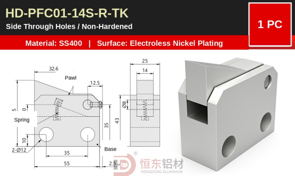 14S example: approximately 55 × 55.5 mm and 25 mm thick
20S and 28S move further into the high-load range. Importantly, model number does not directly equal external size. Some 28S-BK versions are still around 40 × 38 × 12 mm, yet their spring-load range is far above that of 7SA. Two units can therefore look similar in size while being intended for very different operating conditions.
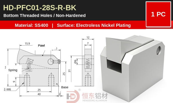 28S-BK example: compact outer size with a substantially higher spring-load range
4. Spring Load: From Around 1 N to More Than 6 N
Because the pawl is returned by a spring, working stroke and spring load are key differences between specifications. The current load table provides calculated values at the assembly position and at Stroke 3, Stroke 5 (7) and Stroke 10 (12). Each cell contains two reference values corresponding to the upper spring position and the front end of the workpiece guide block.
|
Spec. |
Assembly position (N) |
Stroke 3 (N) |
Stroke 5 (7) (N) |
Stroke 10 (12) (N) |
|
7S |
0.4 / 0.3 |
1.1 / 0.7 |
1.5 / 1.0 |
— |
|
7SA |
0.3 / 0.2 |
1.0 / 0.7 |
1.5 / 1.0 |
— |
|
10S |
0.3 / 0.2 |
1.0 / 0.7 |
1.5 / 1.0 |
— |
|
14S |
0.9 / 0.7 |
1.3 / 1.1 |
1.7 / 1.3 |
2.4 / 1.9 |
|
20S |
2.3 / 1.8 |
— |
3.0 / 2.4 |
3.8 / 3.0 |
|
28S |
3.7 / 2.6 |
— |
5.2 / 4.0 |
6.3 / 4.8 |
The difference is significant. 7S, 7SA and 10S mainly cover short-stroke, lower-load conditions; at Stroke 5 (7), their reference value is about 1.5 / 1.0 N. 14S extends to Stroke 10 (12) at approximately 2.4 / 1.9 N. 20S increases to about 3.8 / 3.0 N, while 28S reaches approximately 6.3 / 4.8 N.
This is why the specification cannot be selected by outside dimensions alone. A pallet with a small rebound force and limited pawl depression can use a lighter-load version. A station that requires more pawl travel or a stronger mechanical backstop needs a specification with the corresponding spring-load range.
A useful comparison is 7SA versus 28S. Some versions are both around 40 × 38 × 12 mm externally, yet 7SA is about 1.5 / 1.0 N at Stroke 5 (7), whereas 28S reaches about 5.2 / 4.0 N and continues to 6.3 / 4.8 N at Stroke 10 (12). The installation envelope may be similar, but the working range is not.
5. TK / LK / MK / BK / PK: Mounting Structures for Different Machine Layouts
Even when the pawl and spring specification are correct, the unit still has to fit the machine. Conveyor frames, guide rails, side plates and mounting panels leave very different access conditions. Whether a bolt can pass through the body, whether a nut can be reached from the rear, whether the mounting surface is underneath the unit, and whether the bolt head is allowed to protrude all affect the mounting structure.
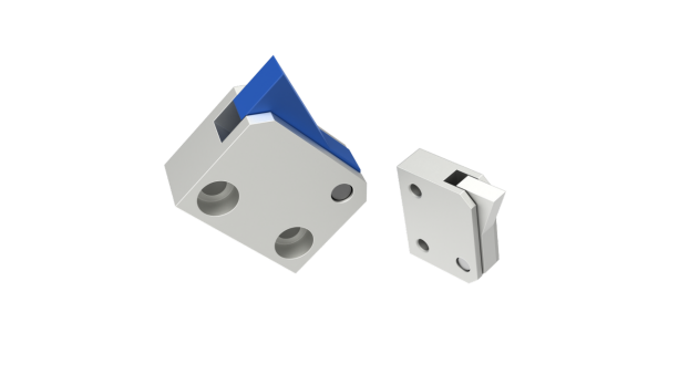 Different PFC body and mounting structures
|
Code |
Mounting structure |
10S representative data |
Typical installation condition |
|
TK |
Side through holes |
2-Ø9 |
Both sides are accessible; bolts can pass through the body |
|
LK |
Side counterbored holes |
Ø6.6 thru + Ø11 counterbore, depth 7 |
Bolt heads must sit below the outer surface |
|
MK |
Side threaded holes |
2-M6 |
Rear access is limited and a nut cannot be conveniently installed |
|
BK |
Bottom threaded holes |
Bottom 2-M6 |
Side mounting is difficult but a support surface is available below |
|
PK |
π-type base |
4-Ø5.5; base width approx. 40 mm |
The unit is mounted directly on a plate, bracket or flat support surface |
TK · Side Through Holes
The 10S-TK version uses two Ø9 side through holes. It is suitable where both sides of the mounting position are accessible and bolts can pass completely through the unit.
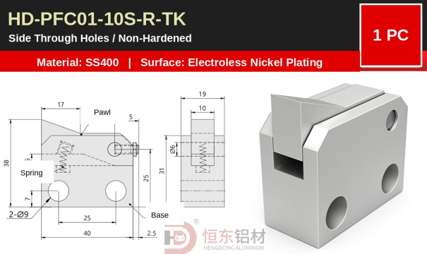 HD-PFC01-10S-R-TK · 2-Ø9 side through holes
LK · Side Counterbored Holes
The 10S-LK version uses Ø6.6 through holes with Ø11 counterbores, 7 mm deep. The bolt heads can sit inside the counterbores instead of protruding from the side surface. This is useful in compact layouts where adjacent parts, covers or moving structures need a clean outer surface.
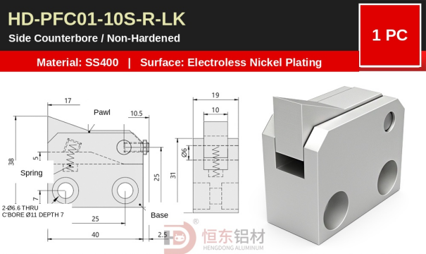 HD-PFC01-10S-R-LK · Ø6.6 through hole + Ø11 counterbore, depth 7 mm
MK · Side Threaded Holes
The 10S-MK version has two M6 threaded holes machined directly into the body. No separate nut is required on the opposite side, making it useful when rear access is limited or the unit must be installed from one side only.
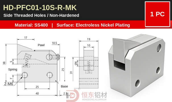 HD-PFC01-10S-R-MK · two M6 side threaded holes
BK · Bottom Threaded Holes
The 10S-BK version moves the fastening points to the bottom of the unit. It is a practical choice where side access is restricted but a mounting surface is available underneath the backstop.
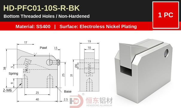 HD-PFC01-10S-R-BK · bottom threaded-hole mounting
PK · π-Type Base
The 10S-PK version adds a π-type mounting base. The representative 10S base is about 40 mm wide and uses four Ø5.5 mounting holes. The side flanges allow the unit to be fastened directly to a machine plate, support bracket or other flat mounting surface.
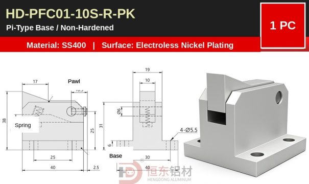 HD-PFC01-10S-R-PK · π-type base with 4-Ø5.5 mounting holes
The backstop function does not change across these mounting versions; what changes is how the unit fits the machine. This is one of the main reasons the PFC range contains many SKUs: the series is designed to cover real mounting conditions rather than force one fastening method onto every machine.
6. Matching the Structure to the Application
|
Typical application condition |
Recommended structure |
Why it fits |
|
Standard steel pallet or metal workpiece carrier |
PFC01 metal pawl |
Straightforward metal-contact solution for conventional industrial use |
|
Aluminum, plastic or surface-finished pallet |
PFC21 MC nylon pawl |
Reduces direct metal impact and is gentler on the contact surface |
|
Very limited installation space |
7S compact specification |
Small body envelope for tight conveyor structures |
|
Limited lateral space with a larger front profile |
7SA |
Approx. 40 × 38 mm front size while remaining about 12 mm thick |
|
General pallet conveyor requiring multiple mounting styles |
10S |
Available with TK/LK/MK/BK/PK mounting options |
|
Longer pawl working stroke |
14S and above |
14S begins to cover the Stroke 10 (12) load range |
|
Higher mechanical backstop load |
20S / 28S |
Stroke 10 (12) reaches about 3.8/3.0 N and 6.3/4.8 N |
There is no simple rule that a larger model number is always better. The correct backstop must match the pallet-contact requirement, installation envelope, pawl depression stroke, required restoring load and mounting access.
By combining different pawl materials, working specifications and mounting structures, the PFC series covers a wide range of real conveyor conditions without requiring the surrounding machine to be redesigned around a single standard part.
7. A Small Component, Built as a Complete Product Family
A pallet backstop is a small component in a complete conveyor system, but its installation position is highly specific. The pallet material, contact height, available space, mounting surface, working stroke and expected rebound force can all change from one machine to another.
For this reason, Henton has expanded the basic spring-loaded backstop into a complete product family: PFC01 and PFC21 for different contact materials; 7S, 7SA, 10S, 14S, 20S and 28S for different structures and working ranges; and TK, LK, MK, BK and PK for different mounting conditions.
The range covers short-stroke applications around the 1 N level through higher-load conditions above 6 N, conventional metal pallets through surface-sensitive workpiece carriers, and side mounting through bottom and flat-base mounting.
Henton PFC01 / PFC21 Pallet Backstop Components are now available.